Milling is a machining
Thanks to its high efficiency, productivity and precision, milling is particularly popular in metalworking production technology. In milling, a distinction is made between 2D milling, 2.5D milling and
What are the basic principles of milling? What processes are there? What materials can be machined?
Milling is a machining process with geometrically defined cutting edges. This means that – in contrast to other manufacturing processes such as grinding, honing or lapping – the geometric contour of the milling cutter is clearly defined. The main component is the milling cutter. This usually has several cutting edges and can be used either perpendicular or at an angle to the axis of rotation. Manual milling machines or entire machining centers are possible.
When milling, a distinction is made between climb milling and up-cut milling. In climb milling, the milling cutter enters the material with maximum stress thickness and exits with minimum thickness. This makes it possible to achieve particularly close tolerances in terms of surface quality. In addition to wood and plastic, almost all metals can also be processed. When milling, a number of parameters must be taken into account so that the desired contours can be achieved and the requirements for certain surface qualities can also be met:
- Cutting speed
The speed has a decisive influence on the cost-effectiveness of the process and depends on the material and cutting material.
- Cutting width
How far the cutting edge of the tool engages in the material depends on the cutting width. Normally, the ratio of cutting width to tool width is approx. 2/3.
- Feed movement
It has a significant influence on the surface quality. The faster the feed rate, the greater the wear on the tool and stress thickness, especially with alloyed and high-alloy steels.
- Pressure angle
- The pressure angle is the angle between the cutting edge entry and exit. It also determines the number of cutting edges in use at the same time. As the number of cutting edges increases, the milling process becomes smoother and more even.
What milling methods are available?
Different processes are used depending on the feed movement and surface processing. The most important milling processes are
What is 2D milling?
In 2D milling, a workpiece is machined in the two spatial directions X and Y. The machining depth Z is determined in advance, permanently set and no longer changed. During machining, the tool paths are in one plane.
What is 2.5D milling?
In this procedure, a workpiece is machined in all three spatial directions X, Y and Z. The infeed depth Z varies during machining without the workpiece having to be reclamped. The change in infeed Z is also known as “line scanning”, as each Z plane is traversed line by line. 2.5D milling can be used to mill bores, countersinks, pockets with vertical sides, roundings, chamfers and also keyways, tenons, threads and even hemispheres.
What is 3D milling?
With 3D milling, workpieces can be machined in all three spatial directions X, Y and Z using a 5-axis CNC milling machine. By dynamically swiveling the milling spindle or clamping table, the tool can be brought to the workpiece at any angle. This milling process can be used to produce 3D contours, true free-form surfaces, spherical surfaces or eccentrics without any problems.
Which machines and tools are used for milling?
Milling machines with at least three axes are required for milling. These can be either manual or CNC-controlled. The latter are much more advantageous and have almost completely replaced conventional systems. Thanks to workshop-oriented programming systems and intelligent tool changers with tool life monitoring, even the most demanding milling work can be carried out at economical prices.
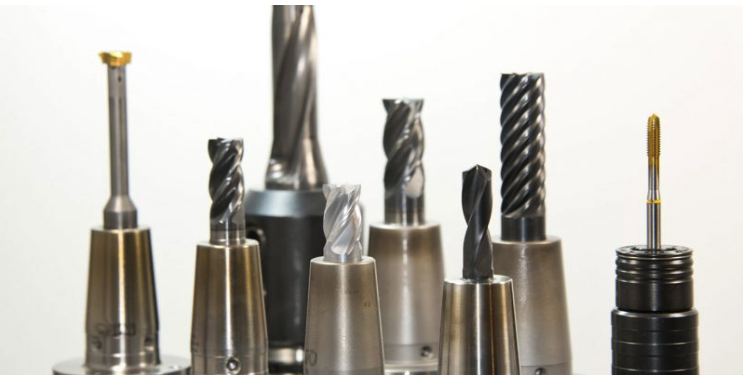
Milling machines require special milling tools that have one or more cutting edges. Rotating movements are used to remove material from the surface of the workpiece. The strategy used, the type of removal and the cutting shape depend heavily on the workpiece to be produced.
Which cutting sizes should be considered when milling?
High-precision molds can only be achieved with optimum parameters. Special attention must be paid to the following parameters:
Which materials are processed during milling?
Milling is a very efficient machining process that can achieve high surface qualities. The most important milling materials include: Steel and cast steel, hardened steels, aluminum and cast aluminum, brass, titanium, gold, silver, bronze, copper, tungsten copper, wood and plastic. Milling is particularly popular in the metalworking industry. Milled parts can be used in a wide variety of industries: Electrical engineering, medical technology, aerospace and also the automotive industry, mechanical engineering and tool and mold making.
What is computer-aided milling?
Milling machines can be operated manually as well as fully automatically and computer-aided. The exact shape of the workpiece can be programmed in advance on the PC, after which the milling machine works independently. In the industrial sector, this has the great advantage that many identical parts can be produced very quickly and automatically.
What is the difference between turning and milling?
Turning and milling are machining production processes: Metals, plastics or wood can be shaped into a predetermined form. Many people often find it difficult to distinguish between the two processes – but it’s quite simple: in milling, the workpiece is stationary and the milling tool moves. With turning, it is exactly the opposite: the workpiece moves around its own axis and makes the cut; the firmly clamped turning tool is guided along the workpiece on a slide. Exceptions are CNC-controlled lathes with additionally controlled axes. With this type of lathe, the tools are also driven.
What is milling?
Milling is a machining process with geometrically defined cutting edges (DIN 8589). Milling can be used to produce flat surfaces and rotationally symmetrical parts. This requires absolutely precise shaping of metal, plastic or even wood – which is why the correct cutting sizes and cutting speed, among other things, are important for milling to exact tolerances. The workpiece is firmly clamped during this process, the milling tool moves along the predetermined contour and removes the material through rotational movements.
How is face milling done?
Face milling can be used to produce flat surfaces with chatter-free tool paths and excellent surface finishes: Circumferential cutting edges chip the material, while face cutting edges finish the surfaces in the same work step. If the milling tool is positioned symmetrically to the workpiece, the force effect of synchronous and counter-rotation is balanced out.
What is a finishing cutter?
Finishing cutters made of HSS steel or carbide belong to the group of end mills. They can be used universally and are available in various geometric designs. This means that every requirement can be met professionally and with absolute precision. With appropriate carrier systems, surface finishes of up to Ra = 0.5 μm can usually be achieved when finishing milling.
What does CAD mean?
CAD is the abbreviation for “Computer Aided Design” and refers to software applications that enable the computer-based design of components. Thanks to special CAD programs, detailed 3D models of desired components can first be designed and then generated. This helps to avoid errors in the run-up to the design process and guarantees optimum functionality of the milled parts produced.